Pneumatic Control System Sketch
The General Design Of A Pneumatic System And Its Components
Basics Of Pneumatics And Pneumatic Systems Ispatguru
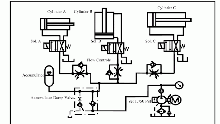
Chapter 5 Pneumatic And Hydraulic Systems Hydraulics Pneumatics
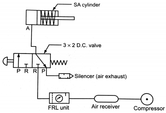
Explain Pneumatic Circuit For Speed Control Of Single Acting Cylinder With Neat Sketch Mechanical Engg Diploma Topicwise Notes And Solutions
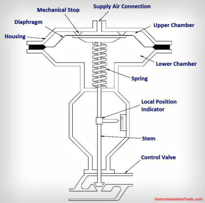
What Is A Pneumatic Actuator Instrumentationtools
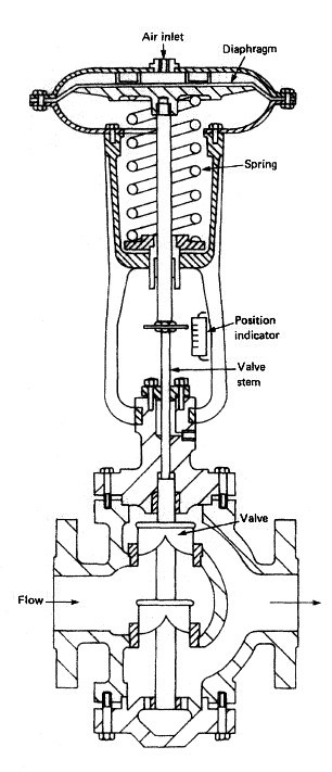
Pneumatic Control Valves For Marine Pneumatic Devices

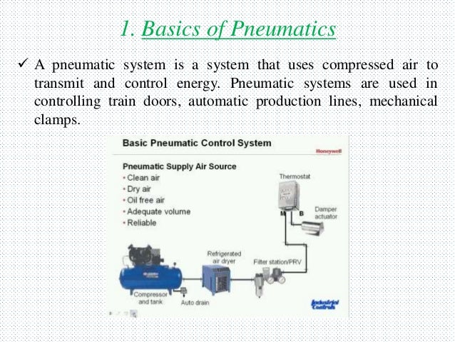
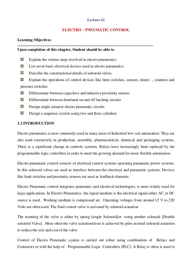
Pneumatic systems are used in controlling train doors automatic production lines mechanical clamps etc fig.
Pneumatic control system sketch. Pneudraw allows you to draw pneumatic circuits quickly and easily. A pneumatic system is a system that uses compressed air to transmit and control energy. This is provided by an air compressor. On off valve pneumatic sketch example double acting with a 5 2 solenoid valve two 3 2 air piloted pneumatic valves and a vessel air tank this sketch could apply to fail close or fail open valve.
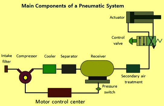
For this same example some suppliers use one 6 2 air piloted pneumatic valve instead of two 3 2 pneumatic valves. A pneumatic system is a system that uses compressed air to transmit and control energy. The pneumatic symbols are linked to the current smc product portfolio. The compressor sucks in air from the atmosphere and stores it in a high.
Pneumatic circuit symbols representing these valves provide detailed information about the valve they represent. Pneumatic circuit symbols explained. An air driven device can use a combination of air for power and oil as the driving medium to overcome this problem but the combination adds cost to the circuit. A automobile production lines b pneumatic system of an automatic machine fig.
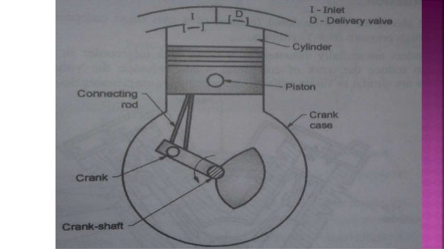
Symbols show the methods of actuation the number of positions the flow paths and the number of ports. 1 common pneumatic systems used in the industrial sector. Most pneumatic systems rely on a constant supply of compressed air to make them work. Directional air control valves are the building blocks of pneumatic control.
A parts list is created automatically in parallel to the circuit plan.

Block Diagram Of The Pneumatic Actuating System 1 Download Scientific Diagram
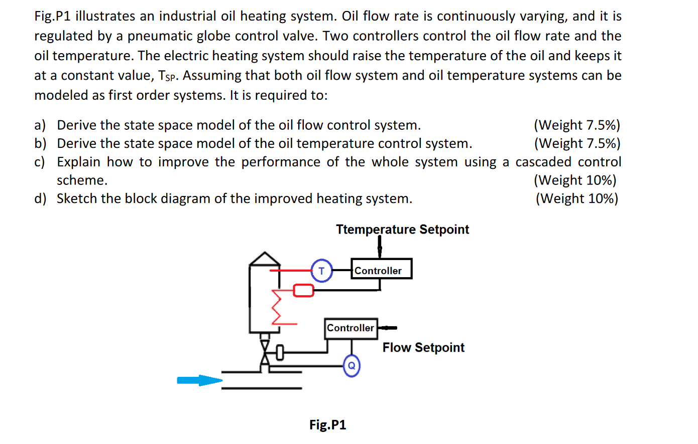
Fig P1 Illustrates An Industrial Oil Heating Syste Chegg Com
Pneumatic Control System
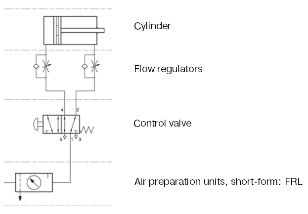
The Basic Components Of A Pneumatic System

How To Analyze And Troubleshoot Hydraulic Circuit Problems Youtube Hydraulic Systems Hydraulic Circuit

Pneumatic Pid Controllers Closed Loop Control Systems Automation Textbook

Pneumatic Controller With A Restriction In The Feedback Path Which Download Scientific Diagram
Http Www Smcpneumatics Com Pdfs Smc Basic Pneumatics Pdf

How To Read A Spool Valve Schematic Drawing Realpars
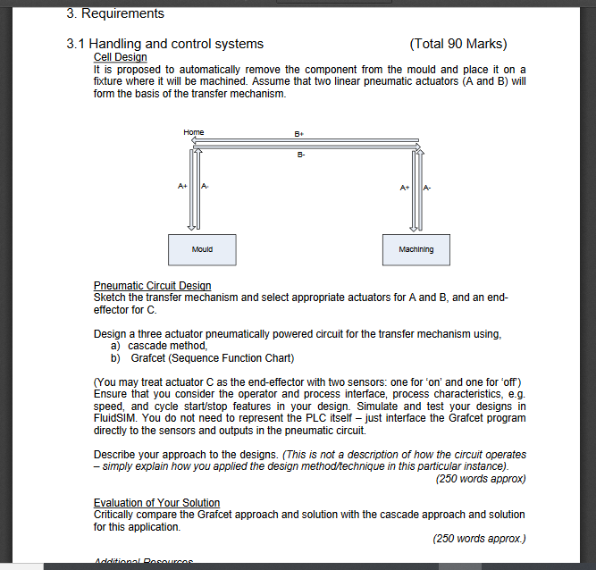
Work Out The Sequence For This System Sketch A Tr Chegg Com
Pneumatic Control System Its Components
Modul Pneumatic

Instrumentation And Control Basic Pneumatics Docsity

